|
|
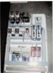
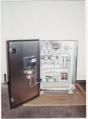
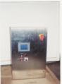
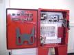
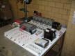
Industrial Control Systems
Today, automation has become a requirement in the
work place in order to maintain a competitive edge over ones competition. CFE’s engineers and
electrical technicians design solutions for upgrading and maintaining plant
operation, and also have the ability of building control panels for the product
being manufactured and sold to the industry.
Contact CFE today for an
estimate to your solutions.
Industrial oils are most commonly concaminted by
water, dissolved hydrocarbons and solids. Water in oil can exist in the
form of free water, emulsified water and dissolved water. Dissolved
hydrocarbons can enter the oil via leaking compressor seals, while solids
can consist of rust particles suspended in the oil. Dissolved gases can cause the following
undesirable effects in lubricating oil: There are four methods of dehydrating
oils: Centrifuging and Coalescing can remove
almost all water but they cannot remove dissolved water. They also cannot
remove dissolved hydrocarbons or hydrogen sulfide. Vacuum dehydration and Air Stripping employ
two methods that remove free, emulsified and dissolved water, entrained
air, dissolved light hydrocarbons and hydrogen
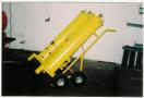
sulfide. The vacuum dehydration unit consists mainly
of a vacuum vessel with the vacuum being pulled by a vacuum pump,
typically to 750 mm (29.6 Hg). A positive displacement inlet pump
circulates contaminated oil from a reservoir through a pre-filter that
removes solids. The oil
continues through a pre-heater, which raises the oil temperature to
approximately 170 degrees F. The flow-through heater is specifically
designed to prevent localized hot spots and carbonization of the
oil. Water, hydrocarbons and other condensables
are flashed off and condensed downstream in a refrigerated condenser
before they reach the vacuum pump. The condensate is automatically drained
from the unit, while the water vapor is vented though the vacuum pump
exhaust. A second positive displacement outlet pump feeds the conditioned
oil back to the reservoir in a continuous cycle. A constantly flooded
suction enables the outlet pump to pull against the vacuum at the rated
capacity of the unit. A final step in the process often consists of a 0.5
micron polishing filter to remove any fines remaining in the
oil. Conditioning is controlled on a timed basis
and samples are taken before and after conditioning for laboratory
analysis to confirm that the oil has returned to its original
specifications. The entire process is normally automatically controlled by
a programmable logic controller (PLC), but manually controlled units are
also available. If an abnormal amount of water or volatiles
is encountered, the temperature and vacuum sensors may signal a
valve to divert the flow back to the conditioner for further processing or
the process may be slowed by other means. This process generally will remove solids
and sludge down to five microns (or less if required) and water content
from more than two percent down to ten ppm. Air and dissolved gases can be
removed from ten percent down to 0.1 percent by
volume. While most lubricating oils contain less
than 1% by weight of additives, such as calcium, phosphorus, sulfur, zinc,
molybdenum, silicones and polymers, etc., the oil conditioning process
will not remove any additives that were previously in the oil. The
purification process will also significantly decrease the acidity as is
evidenced by a decrease in the total acid number. The coalescence of droplets can occur
whenever two or more droplets collide and remain in contact long enough
for the continuous-phase film, which exists around each droplet, to become
so thin that the hole develops and allows the liquid droplets to become
one body. Clean systems with high interfacial tension will generally
coalesce rapidly. Particulates and polymeric films tend to accumulate at
the droplet surfaces and reduce the rate of coalescence. This can lead to
build-up of coalescence, which can significantly enhance the rate of
mass-transfer between phases. The small drops of fine may be caused to
coalesce and thus become larger by passing the dispersion through a
Coalescer. The enlarged drops then settle more rapidly. Coalescers are
mats, beds or layers of porous or fibrous solids whose properties are
especially suited for this purpose. It has been found in studies that
coalescence is promoted by decreased fiber diameter. A minimum bed density
is required to achieve complete coalescence, depending on the system
characteristics. Wetting of the fibers by droplets of the dispersed phase
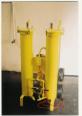
is not necessary for good coalescence. The Custom Filtration Equipment Coalescer
system removes free and emulsified water down to saturation level. The
saturation level is a function of the type of oil, the kinds of additives
in the oil and the temperature of the oil. For typical ISO 32 turbine
light oil at 100 deg. F the saturation level is approximately 150
ppm. The oil first passes through either a
0.5-micron or a 5-micron pre-filter. The pre-filter removes 98% of dirt
particles larger than 0.5 or 5 micron respectively. This prevents the
Coalescer cartridge from being plugged
pre-maturely. From the pre-filter, the oil then flows to
the Coalescer / Separator housing, where it enters from the bottom,
mobbing through the Coalescer cartridges. The oil travels from the inside
to the outside of the cartridge. The Coalescer cartridges filter any
remaining dirt particles down to 10 micron and then coalesce (join
together) all emulsified and free water particles into droplets large
enough to settle out of the oil. The water collects on the outside of the
cartridge. Coalescer cartridges are made of fiberglass
material, which separates immiscible liquids with different densities such
as water from oil. Large (coalesced) water droplets break away from the
cartridge surface and sink to the bottom of the filter housing, where they
are automatically drained by a dual-specific gravity drain
valve. The oil continues through the separator
cartridge, which are in the same housing as the Coalescer cartridges. The
oil passes from the outside to the inside of the separator
cartridges. The separator cartridge is a Teflon-coated
screen, which repels 100% of any suspended water from passing through it
with the oil. The oil is thus separated from any remaining
water. The optional final filter is a 0.5-micron
water-absorbing cartridge, which removes any free or emulsified water
remaining in the oil, as well as any dirt particles over 0.5
microns. Warranty
Custom Filtration Equipment warrants that
products furnished will, at the time of delivery, be free from defects in
material and workmanship. Custom Filtration Equipment will repair or
replace any defects, which occur within one year from the date of
installation or eighteen months from the date of shipment, whichever
occurs first. Repair or replacement of the product will
be, at Custom Filtration Equipment’s option. Products to be examined, and
replaced or repaired at Custom Filtration Equipment’s facilities must be
returned to Custom Filtration Equipment by Purchaser within the warranty
period with transportation charges prepaid. If the examined equipment is
found not to be defective or is not for some other reason within the
warranty coverage, Custom Filtration Equipment service time and other cost
incurred on and off location will be charged to
Purchaser. Purchaser shall be responsible for proper
installation of the units and operation within the design limits of each
unit. Warranty shall not apply if the products are used for any purpose or
under any condition beyond those specified including without limitation;
(1) abuse or misuse, or (2) modification by others, or (3) uses subject to
product abnormal conditions exceeding design
limitations. Correction of defects by repair or
replacement shall constitute Custom Filtration Equipment’s sole and
exclusive responsibility to Purchaser under this Warranty. Custom
Filtration Equipment shall in no event be liable for injuries to persons
or property or direct, incidental, liquidated or consequential damages
caused by use of the product. |
| Copyright © 2003 Custom Filtration Equipment Inc. |